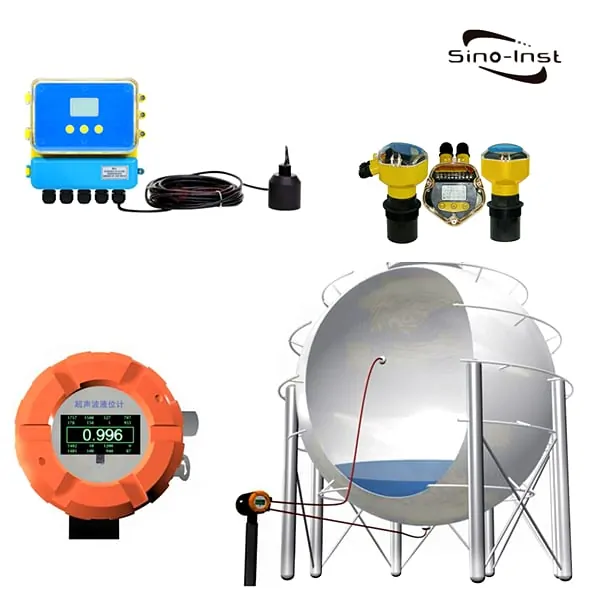
It is able to determine the level of liquid in a medium that is highly corrosive, operates at a high temperature, or is contained in a container that is sealed, all without being affected in any way by the viscosity, density, or working pressure of the measurement medium. This allows it to determine the level of liquid in a medium that is highly corrosive, operates at a high temperature, or is contained in a container that is sealed. An instrument that is known by its name and finds widespread application in the field of automation is known as a liquid level gauge. In addition to this, it is immune to the possibility of becoming obstructed or frozen. In addition to that, it is able to provide precise readings for the measurement of solid powder in addition to granular substances.
The measured static pressure of the liquid is shown to be proportional to the height of the liquid in the submersible liquid level gauge, which works according to the principle that underlies its operation. The gauge makes use of the piezoresistive effect of diffused silicon or ceramic sensitive elements in order to facilitate the conversion of the static pressure into an electrical signal. This is accomplished by the piezoresistive effect. It is able to provide an accurate reading of the distance from the bottom of the water level gauge to the top of the water and can be placed directly into the container or body of water that is being measured. In addition, it can be used to measure the depth of the water.
The core concept that underpins the magnetic flap's bypass pipe is put to use in its construction, specifically in the form of the liquid level structure of the magnetic flap. Both the amount of liquid that is found in the container equipment and the amount of liquid that is found in the primary pipe are the same. The buoyancy and gravity balance that are generated by a magnetic float in liquid are said to float on the surface of the liquid, in accordance with Archimedes' theorem. This occurs as a result of the magnetic float's ability to produce a magnetic field. Above, as the level of liquid in the container being measured rises and falls, the rotating float that is located in the main pipe of the liquid level gauge also rises and falls in accordance with these changes. This allows the liquid level gauge to accurately measure the level of liquid in the container. The liquid level gauge will be able to provide precise readings as a result of this. When using the magnetic coupling table, the permanent magnet found in the float is responsible for causing the red and white turning column found in the indicator to rotate through an additional 180 degrees. This motion is brought about as a result of the fact that the float is attached to the indicator.
The structural component of the magnetostrictive liquid level sensor is made up of several different parts, including a movable float (with a permanent magnet embedded inside), a magnetostrictive wire (waveguide wire), and a stainless steel tube (measuring rod). These parts make up the structural component of the sensor. The structural component of the sensor is made up of these individual parts. As it travels through the waveguide wire, the pulse current will generate a pulse current magnetic field that will surround the waveguide wire completely. You will discover a collection of magnetic rings that are always present inside the float itself. These rings are always there. Because of the interaction between the magnetic field produced by the pulse current and the magnetic ring magnetic field produced by the float, the magnetic field that is surrounding the float will shift as a result of this collision. This change in the magnetic field is what causes a torsional wave pulse to be generated at the location of the float by the waveguide wire that is made of magnetostrictive material. The position of the float, which is equivalent to the position of the liquid surface, can be accurately radar type level measurement determined by measuring the amount of time that elapses between the emission pulse current and the torsional wave. This allows for the accurate determination of the position of the float. This is possible due to the fact that the position of the float is identical to that of the liquid's surface.

The transmission-reflection-reception mode of operation is the one that the radar level gauge utilizes in order to carry out its measurement functions. The readings on the gauge are obtained in this manner. After being reflected off of the surface of the thing that is being measured, these waves are eventually picked up by the antenna. The distance that separates the source of the electromagnetic wave from the surface of the liquid has a direct correlation ultrasonic tank level sensor with the amount of time that passes between the emission of the electromagnetic wave and its reception by the receiving device.

There are in point of fact two distinct varieties of radar level gauges that are put to use in real-world applications: those that use FM continuous wave, and those that use pulse wave. Both of these variations are utilized. The radar pulse wave technology that the liquid level gauge utilizes has a low power consumption and is able to be powered by a two-wire 24VDC supply. Other benefits of this technology include:Using this technology makes it simple to achieve intrinsic safety, high accuracy, and a wider range of application possibilities due to these features' inherent benefits. The sensor will begin the process of the measurement by first emitting a pulse ultrasonic wave, and then the same sensor will receive the sound wave after it has been reflected by the surface of the thing that is being measured. This will continue until the sensor has completed the measurement. After the sound wave has been identified, the same sensor will convert it into an electrical signal after it has been detected. The non-contact measurement, the high reliability, the ease and convenience of installation, and the fact that it is unaffected by the viscosity and density of the liquid are all advantages of this method. In addition, this method possesses both of these benefits. It is also unaffected by the viscosity and density of the liquid, which is yet another advantage of using this method. There is not an exceptionally high level of accuracy, the test might have blind spots, the pressure vessel cannot be measured, and neither can the volatile medium be measured.
The capacitive technology served as the foundation for the development of a novel method of level control that is referred to as RF admittance. It prevents hanging, is more reliable and accurate, and can be used in a wider variety of contexts than its predecessor did. Additionally, it can be utilized in a wider variety of contexts. In the realm of electricity, the reciprocal of impedance is referred to as admittance, and it is a property that is composed of components that are resistive, components that are capacitive, and components that are inductive.
The sensor of the meter, the irrigation wall, and the medium that is being measured all work together to produce an admittance value in circumstances in which the meter is functioning as it should. When there is a shift in the material level, there is a corresponding shift in the admittance value. This happens whenever there is a change. In order to carry out the material level measurement, the circuit unit will perform the necessary conversion of the measured admittance value into a material level signal output. This conversion is necessary for carrying out the measurement. The measurement of the material level can now be carried out on the unit as a result of this conversion.


